|
An
Engineered Design:
Proof in the Details
When
operating the pumping the action
of the water created a ‘thump-thump’
sound so to further investigate the
subterranean chamber’s design I
constructed two more replica orologi model, one to
analyze fluid dynamics within the
chamber and another to analyze the
acoustics of the chamber.
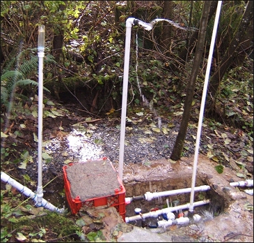
I
used the original pump model I had
modified over the years to create the
acoustic model and built it alongside
a seasonal creek with a small pond
acting as the moat or reservoir. To
endure water pressure and withstand
hydraulic ‘hammer spikes’
fiberglass and epoxy were used to
construct the model. The model was
then cased in reinforced concrete and
when finished weighed 500 pounds.
When
operating, this model generated
powerful pulses that could be felt
through the ground at twenty away feet
and heard a hundred feet away, and
could pump replica rolex datejust uhren water to any elevation
relative to the scale of the Great
Pyramid. Thus, I named it the ‘pulse
generator’ model because of the
powerful pulses generated.
Fitted
with twenty-five ink injectors, the
fluid dynamics model (model #4) was
built with a glass cheap replica sunglasses top and eastern
wall enabling a view of flowing water
inside the chamber. Viewing the water
flow would explain if the pattern of
fins carved into the subterranean
chamber were deliberate. Below are
photographs of model #4’s chamber:
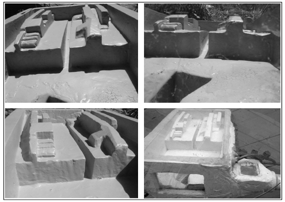
Western View of the Fluid Dynamics
Model's Chamber
In
the above photographs, looking towards
the step gives a perspective of the
fin arrangement. At the upper right
the eastern glass wall is visible with
the pit in foreground. At the lower
right the eastern glass wall can be
seen as well as glass topped ante
chamber. After studying the flowing
water within the modeled subterranean
chamber it is apparent that the flow
of water is dynamic, complex, and
precise.
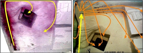
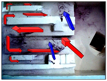
Water flow in model #4
In
the photographs above, at the left,
looking down at the subchamber model
the pit is offset from the eastern
wall to allow for the flow entering
the pit not to interfer with entering
the chamnber from the drive pipe
(yellow arrow). Water that does not
flow into the output (dead end) shaft
is deflected.
At
the right, ink is being injected in
six ports around the “dead end”
shaft. The yellow entrance jet shoots
towards the entrance of the high
pressure output. The orange arrows
show the deflection around the “dead
end” shaft. Notice replica rolex watches how there is a
flow from the ceiling down into the
pit. The pit is offset from the
eastern wall to prevent this
ceiling-to-pit flow from interfering
with the entrance current. This
explains why the pit was offset from
the wall. In the Great Pyramid's
Subterannean Chamber, there is a
sloped area at the top of the pit that
is a result of flowing warer funneling
into the pit. Today, this eroded area
has been filled with bricks to
accommodate hand-rails.
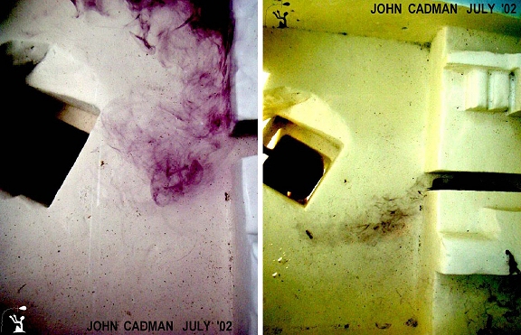
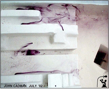
Water Flow in the Step Area of Model
#4
In
the photographs above, looking down on
the step face and the pit the ink
shows the flow running along the face
of the step. As the flow of water
arrives at the step channel it is
diverted. Erosion on the Great
Pyramid's Subterannean Chamber floor
exactly matches this pattern. In the
photograph to the right, ink is
injected into the step channel shows
the flow direction and that the step
channel diverts the face flow.
Interestly,
the pit’s diagonal offset is
precisely aligned with a tunnel that
should lead to an area where the Nile
River existed at one time.
To
continue - please go to John Cadman's
site at:
http://www.great-pyramid-giza-pulse-pump.com/index.php
|
Fluid and Acoustical Dynamics
Sound Refelection Versus Fluid
Deflection
|
|
|
|
|
The
sound wave striking the
perpendicular surface reflects
the majority of the pulse back
towards the source. When the
fluid jet strikes a
perpendicular surface, it
spreads in a 360 degree pattern
perpendicular to the jet. The
subterranean chamber
incorporates fluid dynamics and
acoustical dynamics
|
|
|
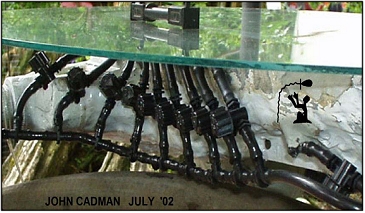
Ink Jets Installed in Model #4
|
|
|
|
|
The
glass topped fluid dynamics
model showing 10 of the 25 ink
injection valves. By placing the
injectors at strategic
locations, the exact fluid
dynamics were able to be
established. Running the glass
topped model in the pump/pulse
mode causes the glass to
immediately shatter.
|
Ink injected into seven ports on the
chamber's step shows the beauty and precision of
the fluid design.
The step and fin structures were
constructed to circulate water around the chamber.
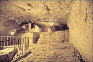
The Great Pyramid's Subterannean
Chamber
with its step and fins feature
clearly visible
The Pulse Pump Model in Action
|