JOHN CADMAN'S RESEARCH
John Cadman's Research Picture Gallery
This is a simple "tee" installed inline instead of the sub chamber. It had major back thrust at the water source. The water quantity pumped was similar, although it was much more erratic.
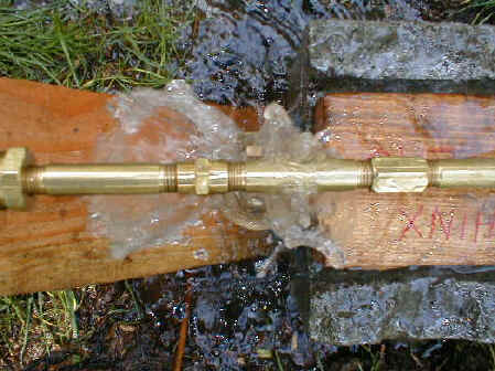
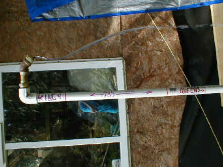
This shows the variable weight lever - brass pipe with miscellaneous fittings screwed on for weights. This is the same assembly which turns purple in the next configuration. The water is from the same source and has the same impurities.
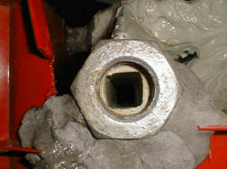
The square shaft and antechamber of the sub chamber were replicated. 1" line allowed for 3/4" square interior. This was the same as 1:48 scale sub chamber.
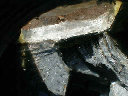
This is the unit which allowed for viewing of the vortex! I never could get it to stop leaking!
Looking down into the tester unit. Notice the fins which adjoin the Eastern wall. This was extrapolated from the "subhole.bmp".
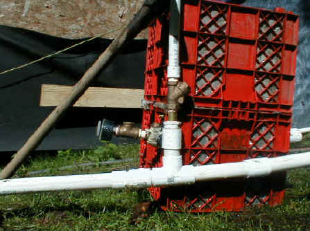
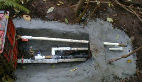
Showing a return line from the wastegate area (parallel pipes from the Sphinx Mortuary Temple), two vertical pipes to test pumping ability to King's Chamber. The lines had a valve to combined the two outputs, or do measurements separately.
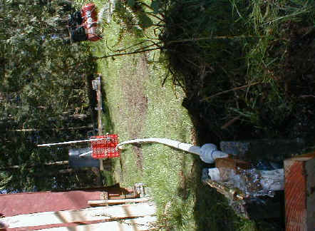
Long shot of the original configuration running in April. No auxillary outputs. The wastegate is the same level as the Sphinx Temple.
This has a secondary output at the grey "tee". This is in the "primarily water pump" mode. With Bobby Schmidt viewing parallel pipes to the Sphinx Temple from the Chefren pyramid, this "tee" output might have been connected to one of those parallel pipes.
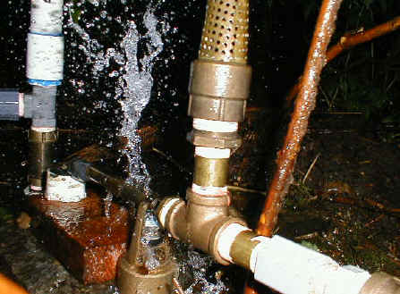
This will be the next testing, when the rain starts falling again and the
seasonal creek fills. The top pipe is the extended dead end shaft. There is a check valve before the
grey "tee". The "tee" allows for a rarefacation wave from the air chamber. The bottom
pipe is the output. At this time, I sent this back towards the sub chamber. It joins in
with an output from the pit/wastegate line. This line has a valve and check valve to
prevent backflow.
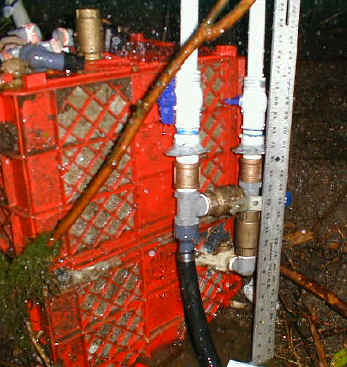
The top pipe (red valve) is the output for the dead end shaft. The bottom line (red
valve also) is the wastegate line from the pit. Here you can see the "tee" which has
two valves . . . one for connection with the deadend shaft output and one for testing
for the potential twist/purple pipe syndrome. To the right of the blue valve is a check
valve. To it's right is a "tee" which connects the deadend shaft output with the final
output (which is the black line).
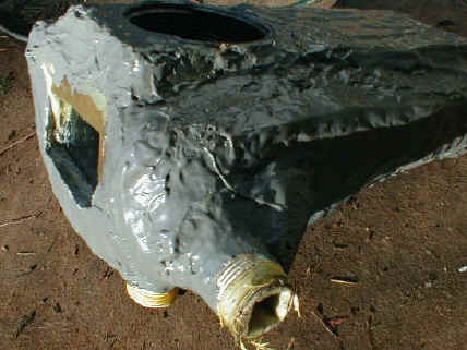
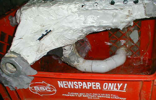
Getting ready to fiberglass a top "recycle bin" to the bottom one. The configuration for the sub chamber can be seen before the 500 pounds of cement is added.
The pipe is the output at the same height as the king's chamber. The pump is running in the "primarily shockwave generator" mode . . . i.e. wastegate but no output by wastegate. It is interesting to note that the waterflow is relatively stable even though there is NO air chamber involved. This same configuration without the sub chamber, but a "tee" in the drive pipe pumped about the same amount of water, but was highly erratic. (Original config. April '00)
![]()